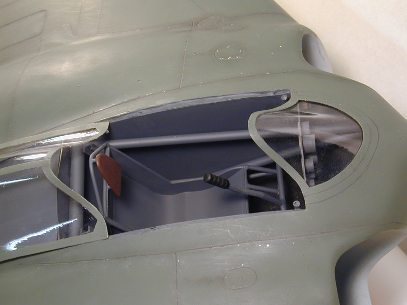
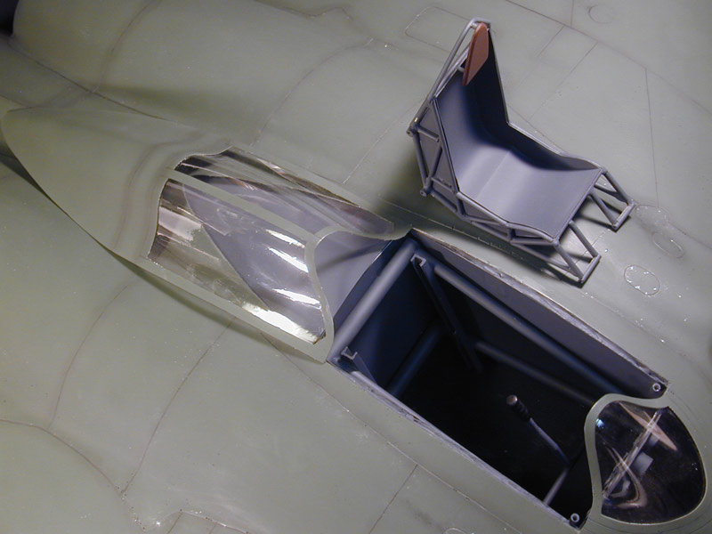
A project to build a model of the Horten Ho 229 V3 cockpit in 1:1 scale. The purpose is to serve as a prop for an upcoming National Geographic documentary on the Ho 229.
Thursday, October 30, 2008
Seat is framed together
I welded the seat halves together this morning. My welds are getting better also. This thing is really strong. I think you'd need a sledgehammer to do any real damage to it once it's done.
Gary
Wednesday, October 29, 2008
Wood parts arrived!
Tuesday, October 28, 2008
Seat progress
News
I should have the wood parts (instrument panel, throttle quadrant, consoles, rudder pedals) any day now, Bob reports they were shipped late last week.
Greg reports he received my canopy plugs for the Ho XVIII yesterday and successfully pulled the parts. I should have those within a few days also.
I should be finishing the welds on the second side of the seat soon, then it will be time to join them.
Gary
Greg reports he received my canopy plugs for the Ho XVIII yesterday and successfully pulled the parts. I should have those within a few days also.
I should be finishing the welds on the second side of the seat soon, then it will be time to join them.
Gary
Monday, October 27, 2008
Seat progress; Ho XVIII
I shut down Sunday night about 5:30, filthy and exhausted, but happy to see at least one completed seat frame. Building up this framwork is slow going, slower than I expected.
I took vacation Thu & Fri, so this represents (together with the instrument panel support framework) over three full days of work. And it's not done yet! I'm sure an experienced welder could work a bit faster. I've been speeding up myself as I gain experience. My welds are improving also. The completed frame is *very* strong.
I'm also working on a small 36" span model of the Ho XVIII "Amerkia Bomber" for the documentary. I'll be including status on that here also for convenience. It's currently in its fourth coat of primer. The canopy/turret plugs are on their way to Greg Smith in Colorado for vacuforming.
Gary
Sunday, October 26, 2008
Instrument panel support and seat framework
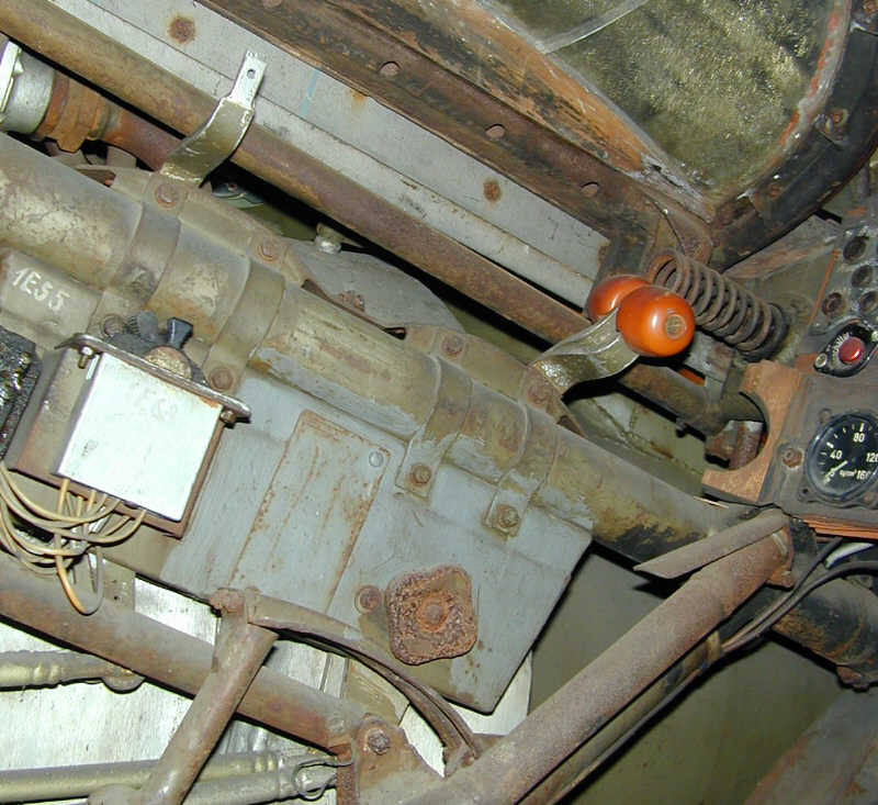
First, here's a picture of the original cockpit framework so you can better see what I'm aiming for. This is the Ho 229 V4, found in the state you see it by advancing allied forces at the end of the war.
Yesterday morning I finished the framework that supports the instrument panel. This framework also supported the rudder pedals in the real a/c, but since I've made it from PVC, I don't think it will be strong enough for that.
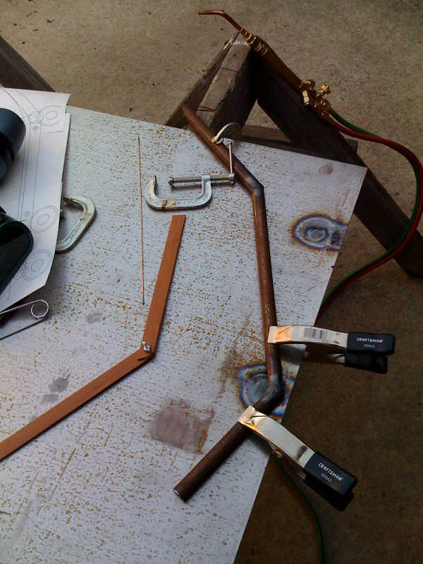
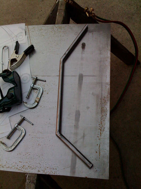
I also did a lot of welding and bending of the seat framework. Also made a jig/template out of press board. I set the template on fire several times :-) You can see the burn marks.
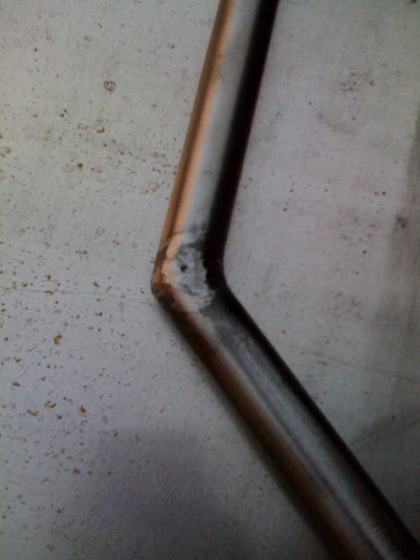
Bending this 3/4" steel tubing turned out to be easier than I thought. I was told the tubing would kink, but I found that with slow, careful application of heat and bending force, it could be done. I didn't need a very sharp bend.
The framework in the picture represents a good 4-6 hours of work. Cutting, grinding/shaping the tubing is the most time consuming part. The actual welding goes pretty fast. I'm starting to get the hang of the welding. Trick is to bring everything just to the melting point together, then it all flows nicely. Accomplishing that can be a bit tricky when you get odd angles and thinner/thicker material to be joined.
Planning to work on the stick and its supporting structure today and hopefully finish at least one side of the seat framework. There are still several interior cross-pieces to go into the framework in the picture. Considered leaving them out, what you see would be plenty strong enough. In the end decided to do it properly :-)
I'm hoping that this cockpit can be displayed by itself somewhere eventually. If so, you will be able to see the sides of the seat, which normally aren't visible through the cockpit opening of the actual a/c.
Gary
Saturday, October 25, 2008
Framework progress; seat welding begins
I've made some progress on the main framework and begun the welding on the seat.
The main ABS framework is now complete. I've begun work on the smaller (1-1/4" diameter) framework that goes behind the instrument panel.
Here's the first part of the side framework. I'm using the 'scrap' steel tubing I got at a local supplier for cheap. They sell it for a few bucks per pound. I'm having to rub the rust off, but that's not a big deal and worth the savings.
Here's the same assembly after cleanup.
My welds are getting a little better... :-)
Here it is laid over the plans so you can see the context.
I'm thinking it may be worth the time to make a jig. Assembly is going to start getting complicated when the two sides are done and it's time to join them!
Just as in soldering, the pieces have to be aligned and held firm (clamped) while the welding is done.
So far I would say that welding like this isn't easy, but it's not rocket science either. Just takes some practice. I can see that to get really good at it would take time. I have a new respect for professional welders though. It's hard work, especially in warm weather! We're having indian summer here and it was in the low 90's while I was doing this.
Gary
Stick grip progress
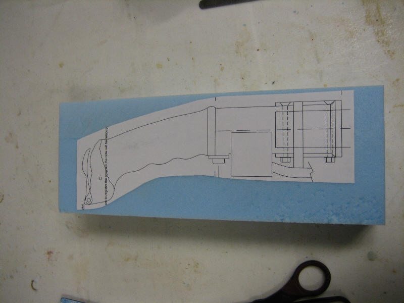
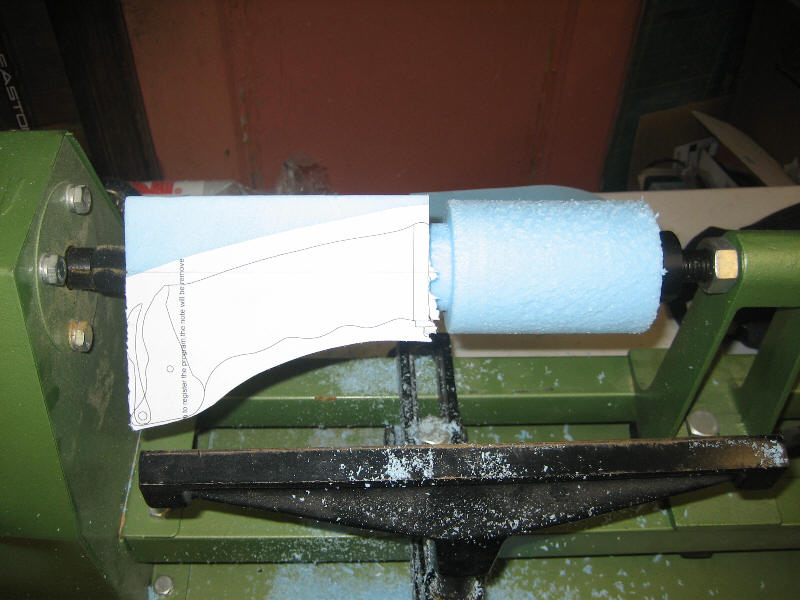
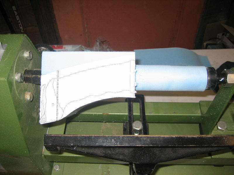
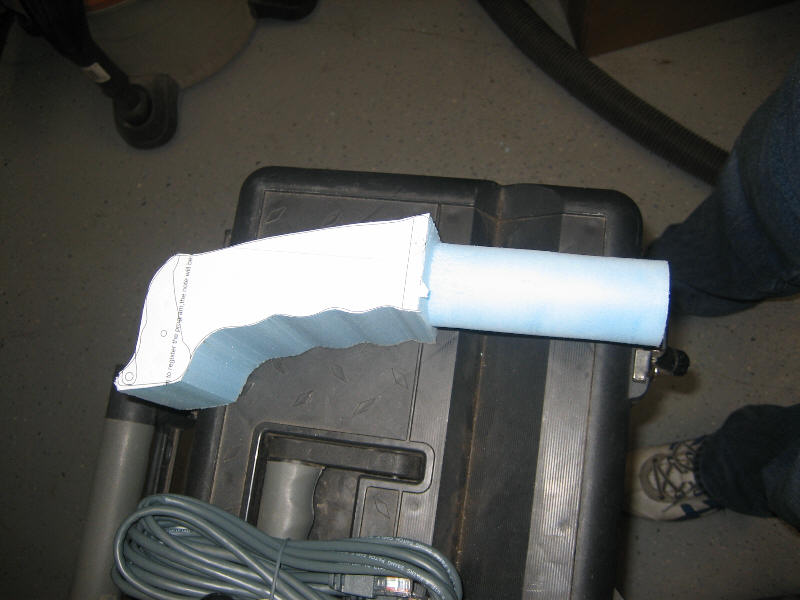
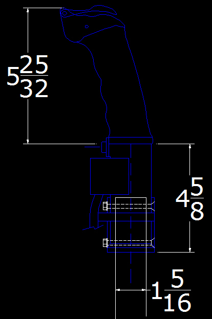
Ian has made some progress on the control column grip...
Thanks Ian and welcome to the project!
Gary
Thanks Ian and welcome to the project!
Gary
Reference; stick grip
Heiner pointed out a great German website with lots of cockpit instrumentation info:
http://www.cockpitinstrumente.de/
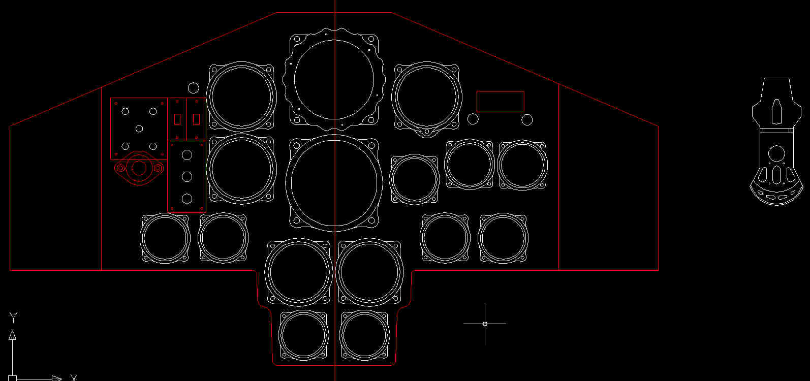
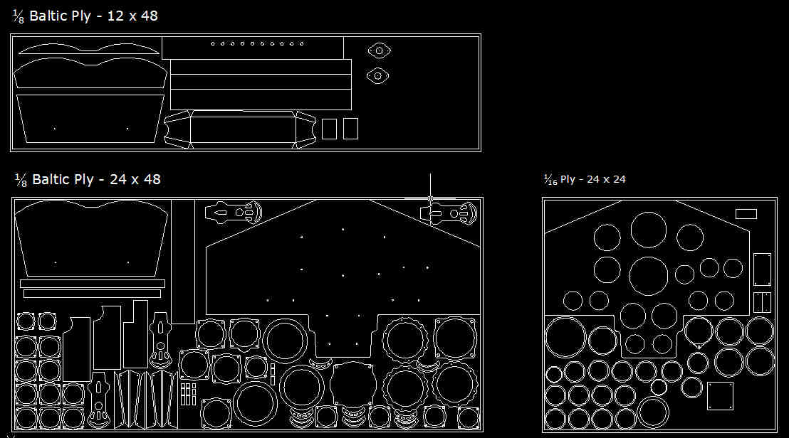
The CAD work is nearly done. Here's the cut sheet for the wood parts:
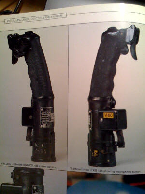
Ian has agreed to make the grip for the control column. This is a really important piece since it is a focal point and everyone is going to want to "take stick in hand" :-) Thanks Ian!!! Here is a CAD drawing I worked up to get him started:
Gary
Basic framework
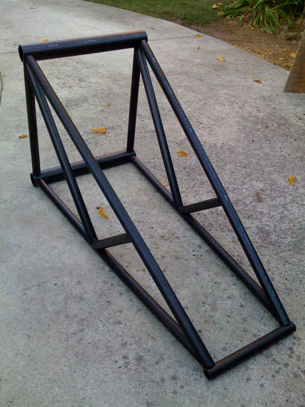
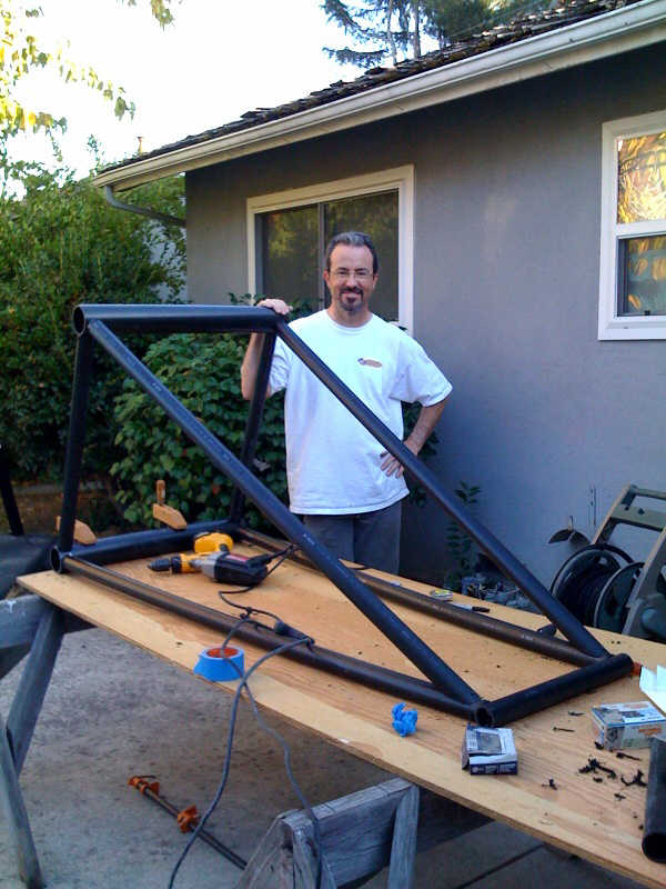
Here's the basic structure I built up on Oct 12 from ABS plumber's pipe. The main spars are 3" pipe, the rest is 2" pipe. Right now it is just held together with screws. I'm experimenting with adhesives to see what will hold the best.
Gary
Gary
Throttle quadrant
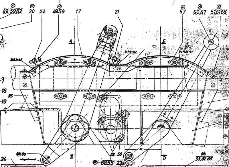
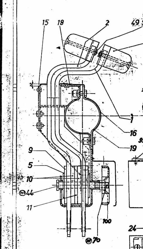
Here's a good example of why I simply *must* do this project! Arthur Bentley kindly sent me scans of all the original German production drawings of the cockpit area. The Ho 229 is one of the few German aircraft from WWII where the original drawings survived. Most were destroyed as the allies advanced unfortunately.
So, the throttle box. I had some good photos of this, here's an example:
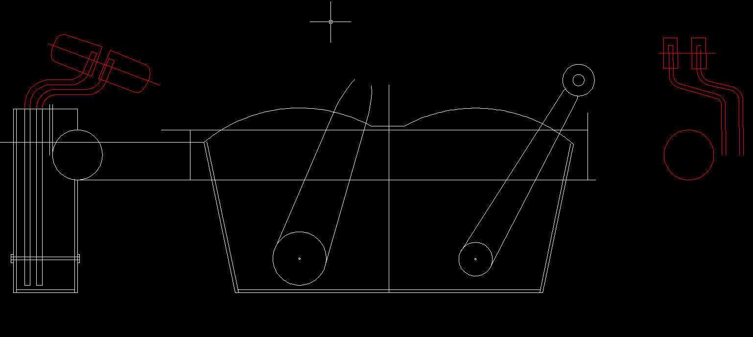
I started on a more or less rectangular box in Autocad, but then I got the drawings from Arthur, turns out the shape is a trapezoid.
And here's the side view showing the throttle handles:
And here's the CAD drawing. I'm simplifying the shape a bit to make it easier to construct. Unfortunately I don't have infinite time to get this thing done.
Today I'm going to start on the framework.
Gary
Control column grip
One thing I could really use help with is the stick handle! I have some really clear photos of it, and dimensioned production drawings. Not an easy shape to reproduce, and it had that textured engraving all over the handle which will be pretty much impossible to reproduce easily. It will also be one of the focal points as everyone is going to want to take the stick in hand and pretend... :-)
Gary
Gary
Volunteers?
If anyone else wants to try their hand at making a German cockpit doo-dad at full scale, let me know. There were a lot of do-dads in this cockpit and I'm not going to have time to build them all!
This mockup will probably end up in a museum somewhere when the filming is done, maybe even NASM since they have the original. Unfortunately time is a bit short for the filming at least, he wants to start filming early in the new year, if not some time in December. But -- small bits could be added to the cockpit pretty much any time.
Gary
Am I nuts or what?
From the moment I learned someone was working on a documentary on the Ho 229 I was hooked. This is one of my all time favorite planes, and I've come to learn I'm far from alone in that.
Some of the details of the documentary are still confidential, but suffice it to say that a cockpit mockup was sorely needed and I volunteered to do it. It is to be used as a prop, but the details of how it is to be filmed are still a bit uncertain.
A little background... Here are a few pics of my 1/8 scale model of the Ho 229 and the cockpit I made for it. This is a flying R/C (radio controlled) model that uses electric ducted fans for power. More on this model at http://www.wingsontheweb.com/ho229/ if anyone is interested.
So the basic idea is to make a more detailed version of this cockpit, only 8 times the size! I'm going to try to make it as realistic looking as possible.
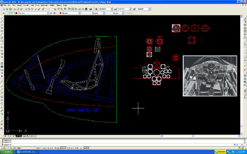
Here are a few shots of the CAD workspace. Not quite sure how this will look munged down to 80K. Should give you an idea though.
My current plan is as follows. Tubular framework made out of ABS and PVC pipe as used for plumbing. Instrument panel & bezels laser cut from ply. Instrument faces will be photo reproductions with acrylic over top.
The seat will be made per the original, welded steel tubing! This is going to be the challenging part since I've never done any welding before. The problem is, I *know* people are going to want to sit in it, and no other material would be strong enough to take the abuse. The stick and other details will be either plywood, PVC or more steel tubing depending on how the welding goes.
I've got my hands on an acetylene welding/cutting outfit. A bit scary but also exciting!!! Ever seen the Beevis & Butthead show where Beevis goes around saying "Fire. Fire." when he's playing with matches? :-) Just have to figure out how to get the job done without burning myself or the house down :-)
Gary
[Work began on this project at the beginning of October, 2008. I created this blog on Sat Oct 25 and copied the content from the original blog on RCSCALEBUILDER.com]
Some of the details of the documentary are still confidential, but suffice it to say that a cockpit mockup was sorely needed and I volunteered to do it. It is to be used as a prop, but the details of how it is to be filmed are still a bit uncertain.
A little background... Here are a few pics of my 1/8 scale model of the Ho 229 and the cockpit I made for it. This is a flying R/C (radio controlled) model that uses electric ducted fans for power. More on this model at http://www.wingsontheweb.com/ho229/ if anyone is interested.
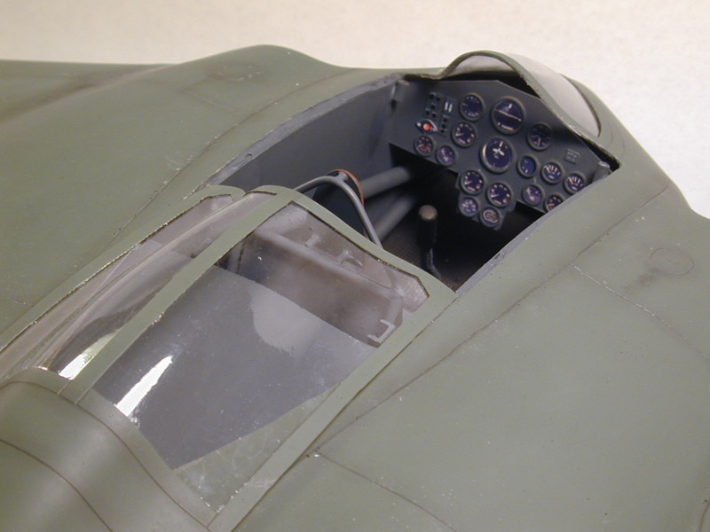
So the basic idea is to make a more detailed version of this cockpit, only 8 times the size! I'm going to try to make it as realistic looking as possible.
Here are a few shots of the CAD workspace. Not quite sure how this will look munged down to 80K. Should give you an idea though.
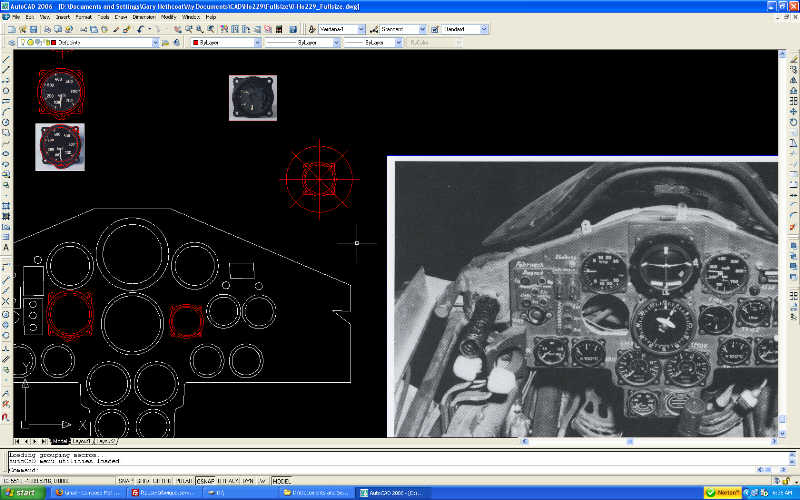
My current plan is as follows. Tubular framework made out of ABS and PVC pipe as used for plumbing. Instrument panel & bezels laser cut from ply. Instrument faces will be photo reproductions with acrylic over top.
The seat will be made per the original, welded steel tubing! This is going to be the challenging part since I've never done any welding before. The problem is, I *know* people are going to want to sit in it, and no other material would be strong enough to take the abuse. The stick and other details will be either plywood, PVC or more steel tubing depending on how the welding goes.
I've got my hands on an acetylene welding/cutting outfit. A bit scary but also exciting!!! Ever seen the Beevis & Butthead show where Beevis goes around saying "Fire. Fire." when he's playing with matches? :-) Just have to figure out how to get the job done without burning myself or the house down :-)
Gary
[Work began on this project at the beginning of October, 2008. I created this blog on Sat Oct 25 and copied the content from the original blog on RCSCALEBUILDER.com]
Subscribe to:
Posts (Atom)